Welcome to That Maker Show with me, chalkers, your host to all things new in the maker movement.
This week we’re talking about, hassle free 3d printing, talking toys, insults and an awesome kickstarter project
Ninja Plate Flexible Build Platform
Over on the Adafruit YouTube channel there’s a video demonstrating the Ninja Plate Flexible Build Platform. Instead of using tape, glue or hairspray on your Makerbot Replicator 2’s build plate, you pop the ninja plate on top of it and print directly on that.
Once you’re done with your print take the plate off and twist it a little and your print will just pop off.
The 3dprinterninja.com site they’ve currently sold out, but you can subscribe for updates for stock notifications.
GEMMA Talking Toy Sound Pack
Adafruit released this week a project for their GEMMA platform.
If don’t know what GEMMA is it’s a tiny arduino compatible, wearable module. The project kit includes all the components necessary to make a toy that plays a sound when you pick it up and give it a little wiggle.
The amazing Becky Stern shows you how to wire this project together in a video on their YouTube channel and I’ll include links get your hands on these kits in the show notes. You can even buy a cute Sew-Your-Owl-Kit.
You insert a coin, push a button and it prints out an insult on a receipt, lovely!
He builds the project live and you can follow along. I’ll include a link to the parts in the show notes.
OSCAR
Now, I want to share a cool Kickstarter Project. OSCAR. And it ends next week and it needs your help.
It’s basically a high resolution iPad screen that’s been broken out so that can be plugged into a regular mini-display or thunderbolt port. It’s enclosed in an awesome clear acrylic stand.
The cool thing about it is it’s open source hardware and software and the breakout board on the back of the display has jumpers so your can customise it with sensors and custom circuits. It’s also arduino compatible!
It’s very similar to Adafruit’s Qualia display but it seems to be even easier to started hacking on it.
Both the Qualia display and OSCAR are at similar price point. I already have a Qualia and love it. If you want an easily hackable iPad display show your support on the kickstarter project.
Outro
Thanks for watching, remember to subscribe for your weekly dose of maker news.
Notable mentions
Hit me up @chalkers on twitter if you have any stories you’d like me to cover. If they don’t make it into the show I’ll include them as notable mentions in the show notes.
Tonight was the last Saturday night Adafruit Industries Show and Tell. They’ll be moving over to Wednesday nights from now on.
I went on it to share my latest project, The Extremely Remote Controlled Car. This is where I take a $9 RC car from Walmart, wire it’s remote up to an Arduino, and control it over a serial port connection with Node.js. You can use your mouse and keyboard keys. But I’m not one to discriminate against other devices. You can use your browser on iOS devices or even a Nintendo Wii U Gamepad! It was a great experience and was a full packed show. Cats, robots and lizards!
LadyAda, Adafruit Industries’ founder Limor Fried, said it was one of the “best ever” shows. Judge for yourself below.
I think every Show and Tell is the best ever because people are making stuff. It’s always an inspiration. After watching last week’s show I felt compelled to make my project.
Code
I’ll be doing a full write up on how I made the Extremely Remote Controlled Car but until then the code is open source on GitHub.
After getting my Arduino-controlled RC car turning right, I was just preparing to solder a wire on to turn the car left to the remote control’s circuit board. But it wasn’t going to be the case. I knocked my Panavise Jr. PCB holder off of the table I was working on. And this happened:
When it happened I didn’t feel frustration. Upon reflection I’ve learnt more than the value of the $9 I spent on the car and replacing it isn’t that expensive. I’ll have a spare car or I can control 2 at once! How wicked is that?
I probably would be able to re-solder wires quicker and cleaner thanks to some tips I picked up from a colleague, Tommy Wingo, at lunch today.
Mistakes and accidents happen. They’re teaching moments. I now know I should either:
Keep your PCB holders away from the edge of the table
Keep them secured to the table
Breaking things is fine. Brush yourself off and get back to it. Now, I’m off to Walmart, it’s open all the time, I love America.
Last night I picked up a Ford Mustang 1:24 Scale Radio Control Sports Car from Walmart for under 9 bucks.
I’ve seen electronics enthusiasts and makers buy cheap RF cars and use parts for their projects. For example this cute Wall-E robot.
I wanted to see if I could use an Arduino to control the RC car.
Test Everything, All the Time
So before I did anything, I tested that the car actually worked. This is to determine if what I was going to do next didn’t break the thing.
I noticed when pressing forward/backward and left/right there was no granularity to the speed or turning. I heard clicking. It seemed there were just buttons controlling it. This means it should be fairly simple to hack and send signals from the Arduino.
Breaking In
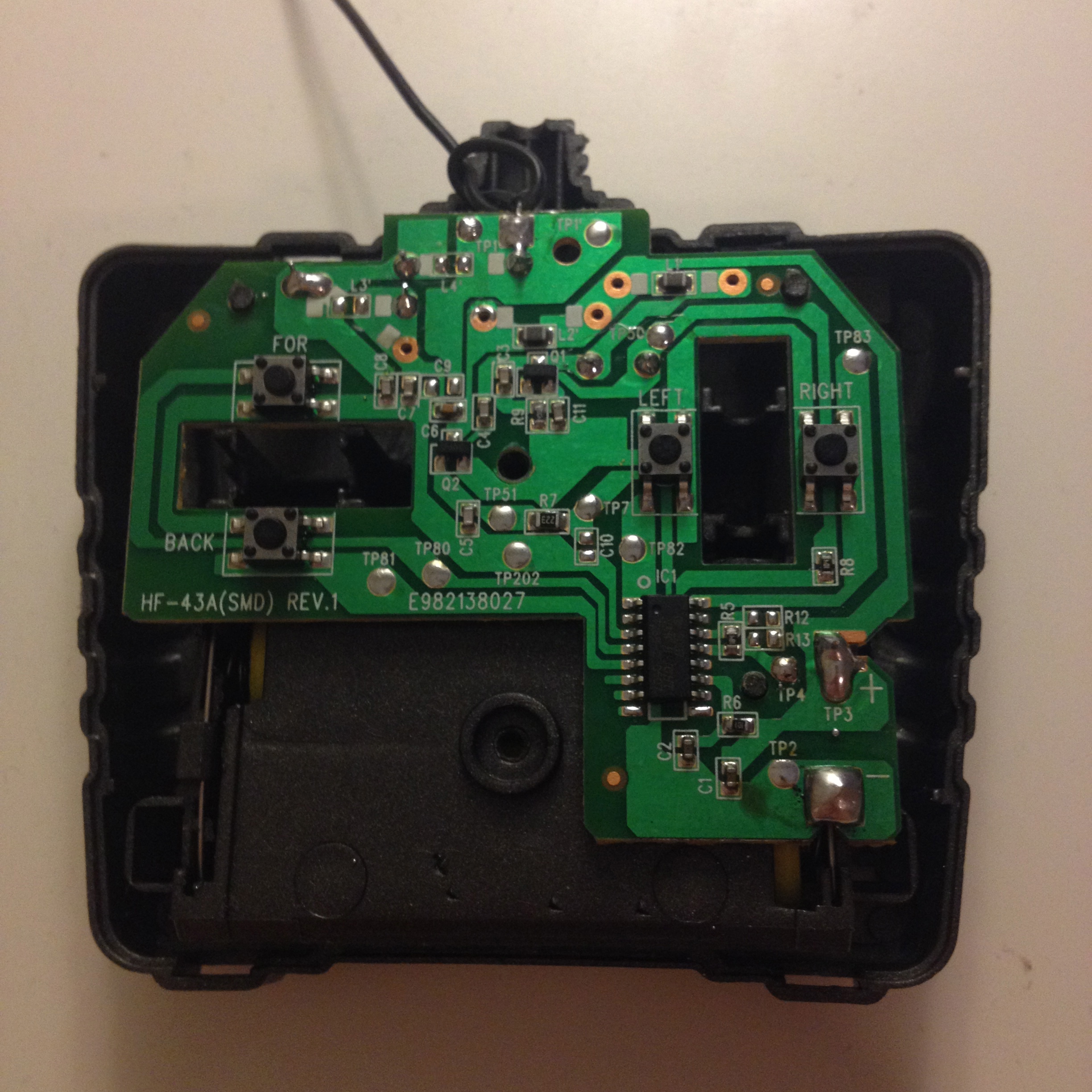
So the first thing I did was remove the screw from the back (and a sticker) that would prevent me from opening up the remote.
As you can see, as suspected, there are buttons for going forward (FOR), backward (BACK), left (LEFT) and right (RIGHT). I’ll use these later on. Whilst still attached to the back of the case I tested to see if pressing the buttons directly moved the car. It still worked.
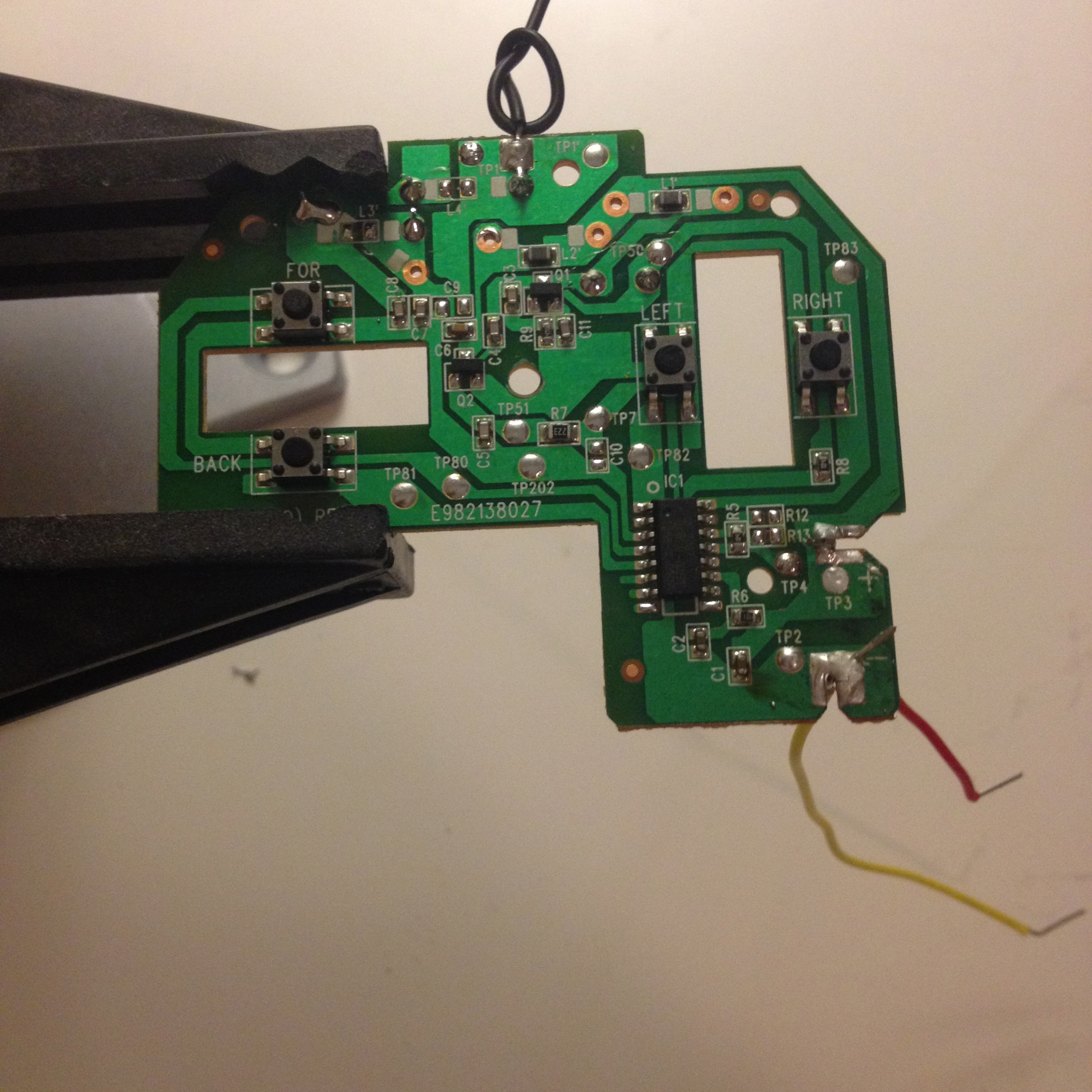
Next, getting the remote off the dependancy of the two AA batteries so that the remote could be powered by the same source as the Arduino. Since each AA battery is 1.5V, the two will create a voltage of 3 volts. The Arduino has a 3.3V header, so I thought I could power the controller it with that.
I desoldered the original connections to the battery compartment and soldered two wires, red to the positive and yellow to the negative (don’t have any black wire ;)).
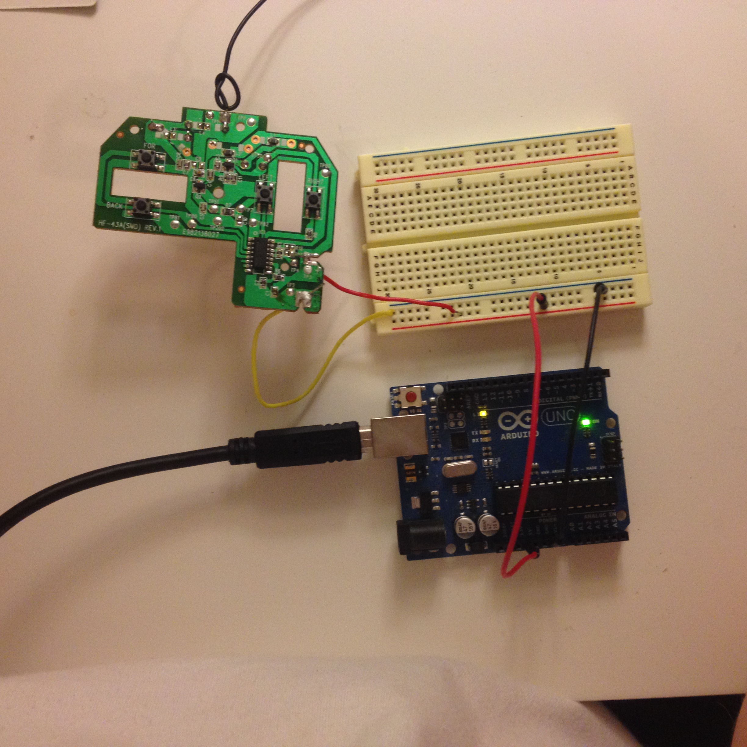
I wired it up and pressed the buttons on the remote and the RC car still worked. At this point a second car that I got for my daughter to play with started moving slightly in response to the button presses. My car is at 27 MHz and my daughter’s is at 49 MHz. So I don’t know if exposing the circuit is causing interference with the other car or if I damaged it in someway. However, the signals from her controller overrides my interference so there’s not a big issue here.
So now I had the power working, now on to programatically pressing the movement buttons. I could have desoldered the buttons and added another wire in it’s place but I followed the switch wire back around to a spot on the circuit board that said TP80. Now there’s several of theres TP points all over the circuit board. I thought that these could be places on the board that could be used for testing circuit boards during manufacture. Maybe some sort of test point? So I soldered a wire on to TP80 to see if I could programatically send a HIGH or LOW signal to pin 13, like the “blink” of controlling a RC car and I got the following result:
It went forward for a second stopped for a second and so on until it hit an object! Not bad! And the buttons are still in tact too!
So I wired up TP81 to pin 12 and made the car go backward and forward for one second. And yep it worked.
Conclusion
And that’s where I got up to last night. Being an absolute beginner to electronics and getting an off-the-shelf product like this to be programmable is pretty amazing and fulfilling.
The only thing that’s stopping anyone from doing anything like this, or anything for that matter, is themselves.
Getting a remote control car for under 9 bucks is way cheaper than building something like this from scratch.
Next Steps
I want to be able to programatically turn the car and who know’s what else? Maybe using computer vision libraries to process video from a webcam and talk down a serial connection to the Arduino to control the car automatically? Any ideas? Let me know.
Code
The code for this project and it’s dependancies can be found below:
BasicLibrary - used for the object orientated interface with digital/analog pins
RC_Back_Forward - code for making the car go forwards for a second then backwards for a second
I bought an Xbox Kinect late last month as I wanted to use it to scan in my daughter to get printed out at Shapeways or a similar service for a present for my Gran’s birthday.
I had seen software like ReconstructMe and others like Skanect on YouTube which have the ability to scan using a Kinect.
I then found myself wanting to experiment with the live data coming in from the Kinect. And I didn’t really know where to start.
Since I’ve been playing around with Arduino I thought I’d see if Processing had a way to interface with it. The Arduino programming environment editor is a derivative of the Processing editor. So I thought there would be some familiarity there.
I then Googled processing with kinect and came across this post by Daniel Shiffman which provided a library to interface Kinect with Processing.
I then opened up the point cloud example (shown above) and proceeded to hack for the evening, tweaking, reverse engineering Daniel’s source code and learning keyboard inputs with Processing and after a little while I came up with this matrixy style hologram of myself with keyboard controlled rotation. (There’s no audio.)
If this has peeked your curiosity in to Processing check out the Hello World! Processing documentary below:
Button         HEX
-------------- -----------
Pause/Play     0x77E12047
Menu           0x77E14047
Volume Up      0x77E1D047
Volume Down    0x77E1B047
Rewind         0x77E11047
Fast Forward   0x77E1E047
I wanted to use each key press to do something. I did Pause/Play to stop and start the buzzer, volume up and down to change the tone, rewind to slow down the frequency of tones and fast forward to increase the frequency.
if(currentMillis - previousMillis > between + beeplength ) {
previousMillis = currentMillis;
if(isOn)
{
tone(speakerPin, tones[i]);
}
}
if(currentMillis - previousMillis > beeplength) {
noTone(speakerPin);
}
if (irrecv.decode(&results)) {
switch(results.value)
{
case MENU:
break;
case PLAY_PAUSE:
isOn = !isOn;
break;
case VOLUME_UP:
i++;
break;
case VOLUME_DOWN:
i--;
break;
case REWIND:
between= between + 100;
break;
case FAST_FORWARD:
between= between - 100;
break;
}
if(i > numTones) {
i = numTones;
}
if(between > maxTime) {
between = maxTime;
}
if(i < 0) {
i = 0;
}
if(between < 0) {
between = 0;
}
irrecv.resume();
}
}
Gotcha
I got this compile error:
core.a(Tone.cpp.o): In function `__vector_7':
/Applications/Arduino.app/Contents/Resources/Java/hardware/arduino/cores/arduino/Tone.cpp:535: multiple definition of `__vector_7'
IRremote/IRremote.cpp.o:/Users/andrew/Documents/Arduino/libraries/IRremote/IRremote.cpp:311: first defined here
In order to use tone() with the IRremote library I had to modify IRremoteInt.h in the libraries/IRremote folder on to use IR_USE_TIMER1 on line 66 and commented out IR_USE_TIMER2. I don’t fully understand this yet, other than there was some sort of conflict going on, but that’s how I got it to work, and that’s the important thing!
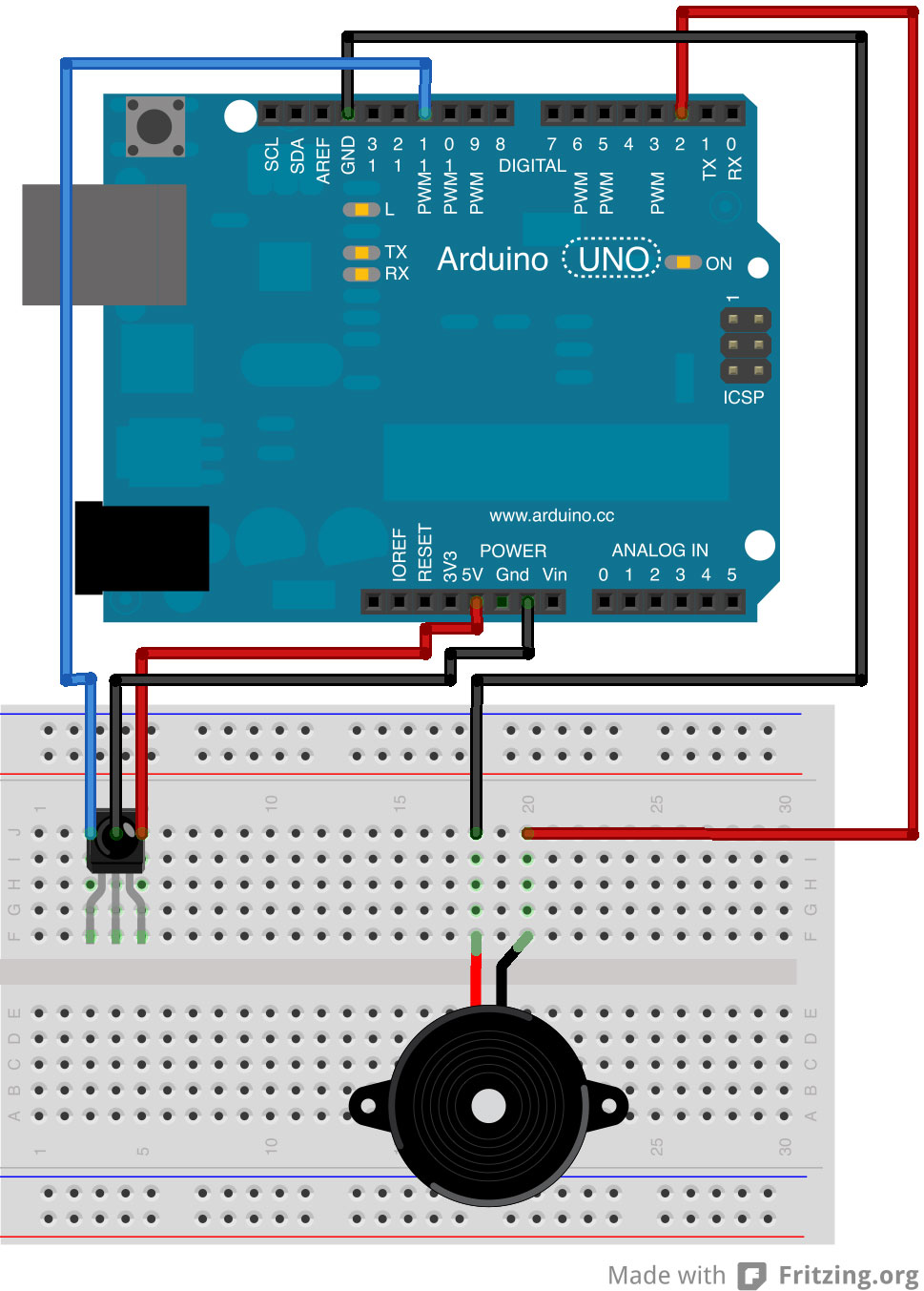
I wired up the buzzer to pin 2 and ground. It doesn’t matter which leg of the buzzer goes to which. With the curved surface of the IR sensor facing toward me, I wired the first leg to pin 11, the second leg to ground and the third to power (5V).
Conclusion
It’s pretty amazing what you can do with a few bucks of electronics with an Arduino and I am starting to feel that less and less things are beyond my grasp, which is a great feeling. I feel I’ve learned a lot already and have made mistakes along the way, but without those mistakes I wouldn’t have learned so much!
Arduino is an open-source electronics prototyping platform based on flexible, easy-to-use hardware and software. It’s intended for artists, designers, hobbyists, and anyone interested in creating interactive objects or environments. Source: http://www.arduino.cc/
Microcontroller
Arduino is a microcontroller on a circuit board which makes it easy to receive inputs and drive outputs.
A microcontroller is a integrated computer on a chip.
Inputs
Some examples of inputs would be a temperature sensor, a motion sensor, a distance sensor, a switch and so forth.
Outputs
Some examples of outputs would be a light, a screen, a motor and so forth.
TL;DR
Arduino is a small computer that you can program to read and control electrical components connected to it.
Obtaining an Arduino Board
There are several online distributors that stock Arduino boards.
Often boards are bundled up with starter kits. Kits include a wide variety of inputs, outputs, resistors, wires and breadboards. Breadboards are solderless circuit prototyping boards that you can plug wires and components into.
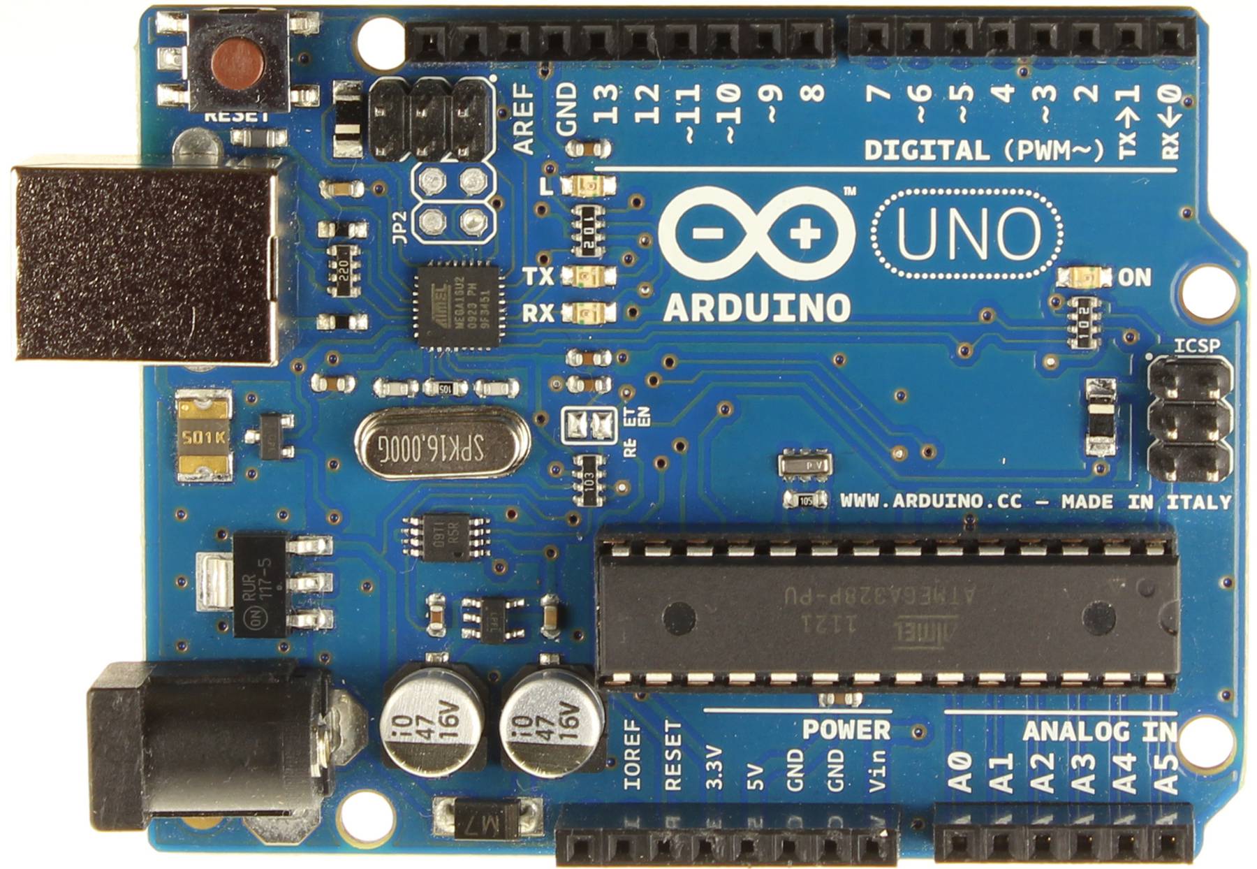
Arduinos come in different flavours. Most people starting off go for the UNO board. It’s current revision is the third, hence the R3 listed by stockists.
You can even pick up one from your local RadioShack.
A more complete list of distributors can be found on the Arduino Distributors page.
If you’re just getting a single Arduino board or starter kit be sure you have a USB A to B cable. Most, if not all, starter kits come with the USB A to B cable. Most printers have this type of interface so you may have this cable already lying around. The reason you need the cable is to program the device so it’s best to double check when ordering.
Programming Arduino
For the example I’m showing you’ll only need the Arduino UNO R3 board itself and the required USB cable to transfer the program from your computer to the board.
On the board left of the Arduino logo there’s an LED, short for Light Emitting Diode, a small light, with the letter L next to it.
We’re going to switch it on and off and then look in to making it blink on and off for 2 seconds at a time.
When you first plug your USB cable in to your Arduino and your computer, you may notice that this LED is blinking. Not to worry! It’s the default program stored on the chip. We’re going to override this.
The USB cable powers the device. Arduinos can run standalone by using a power supply in the bottom left of the board. Once you’re done programming and don’t require it to be constantly connected to your machine you can opt to power it separately. This is entirely dependant on the use case and circumstances you want to use the device in.
Download Arduino Software
You’ll need to download the Arduino Software package for your operating system from the Arduino download page.
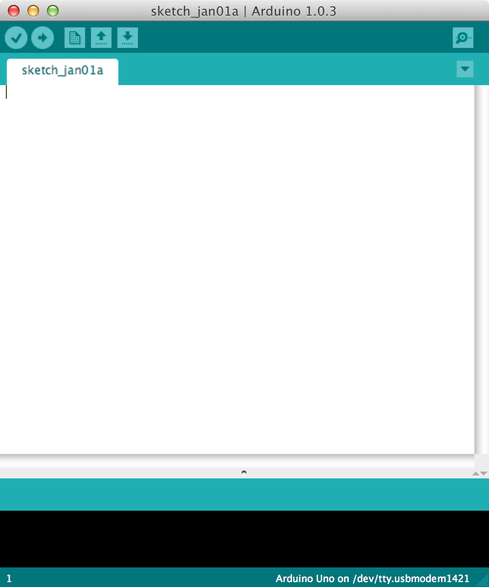
When you’ve downloaded and opened the application you should see something like this:
This is where you type the code you want to compile and send to the Arduino board.
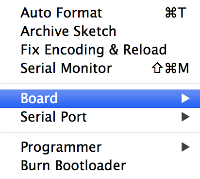
The Initial Setup
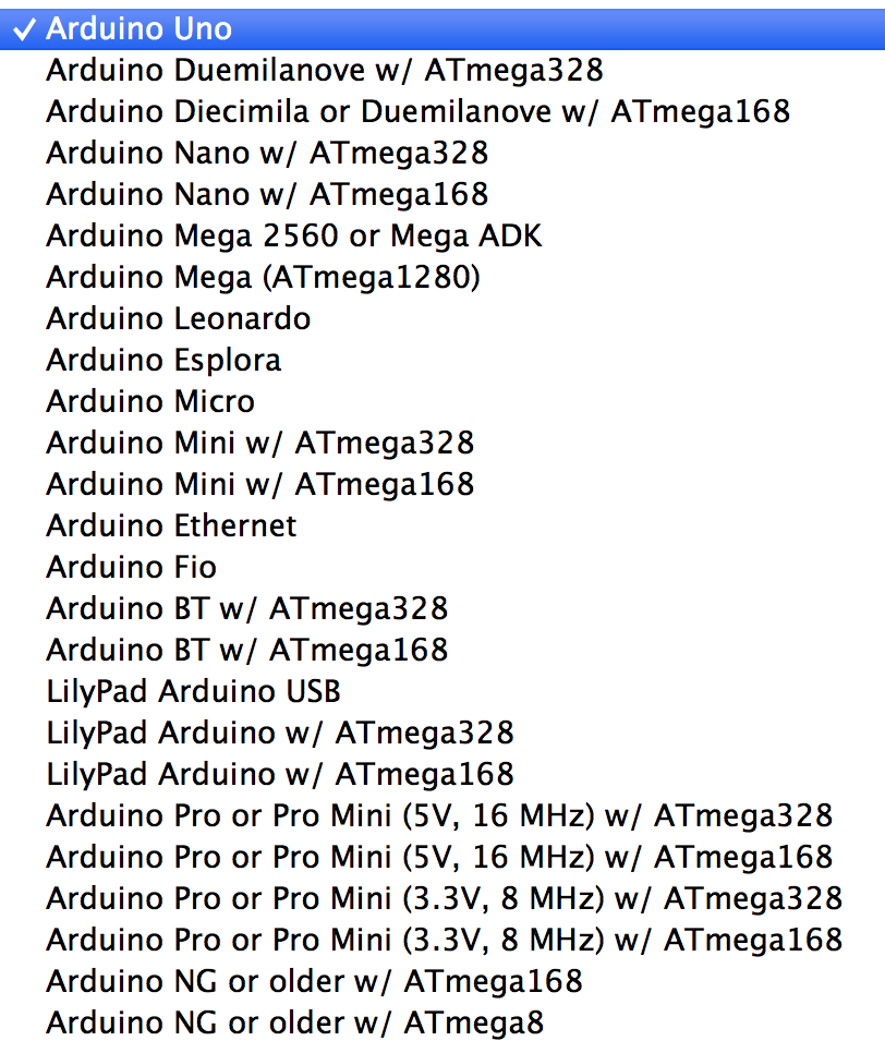
We need to setup the environment to Tools menu and select Board.
Then select the type of Arduino you want to program, in our case it’s the Arduino Uno.
The Code
The code you write for your Arduino are known as sketches. They are written in C++.
Every sketch needs two void type functions, setup() and loop(). A void type function doesn’t return any value.
The setup() method is ran once at the just after the Arduino is powered up and the loop() method is ran continuously afterwards. The setup() is where you want to do any initialisation steps, and in loop() you want to run the code you want to run over and over again.
So, your basic sketch or program should look like this:
1
2
3
4
5
6
7
8
9
voidsetup()
{
}
voidloop()
{
}
Now we have the basic skeleton in place we can now do the Hello, World program of microcontrollers, a blinking an LED.
Headers and Pins
If you notice on the top edge of the board there’s two black rectangles with several squares in. These are called headers. Headers make it easy to connect components to the the Arduino. Where they connect to the board is called pins. Knowing what pin something is connected to is essential for programming an Arduino.
The pin numbers are listed next to the headers on the board in white.
The onboard LED we want to control is on pin 13.
In our code above the setup() method let’s create a variable called ledPin. In C++ we need to state why type our variable is before hand, in this case it’s an integer, so it’s of type int.
1
2
3
4
5
6
7
8
9
10
11
int ledPin = 13;
voidsetup()
{
}
voidloop()
{
}
Each line is ended with a semicolon (;).
In the setup() method we want to set the ledPin to the output mode. We do this by calling a special function called pinMode() which takes two variables, the first the pin number, and second, whether it’s an input or output pin. Since we’re dealing with an output we need to set it to a constant called OUTPUT. If you were working with a sensor or input it would be INPUT.
1
2
3
4
5
6
7
8
9
10
11
int ledPin = 13;
voidsetup()
{
pinMode(ledPin, OUTPUT);
}
voidloop()
{
}
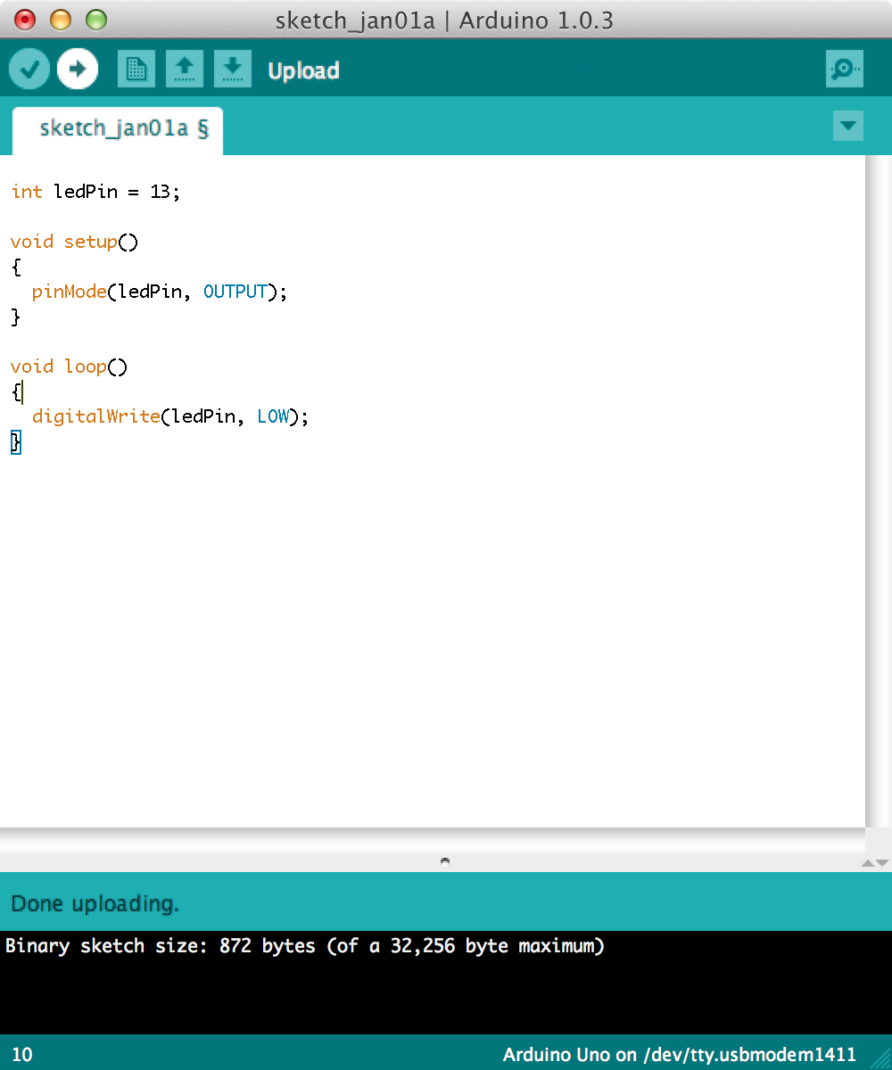
In our loop we are going to first switch off the LED to make sure our program is being transferred to the chip and overriding the default.
We do this by calling another special method called digitalWrite(). This also takes two values, the pin number and the level, HIGH or the on state or LOW the off state.
1
2
3
4
5
6
7
8
9
10
11
int ledPin = 13;
voidsetup()
{
pinMode(ledPin, OUTPUT);
}
voidloop()
{
digitalWrite(ledPin, LOW);
}
Next we want to compile to machine code and deploy or upload it to the Arduino.
Compiling the Code
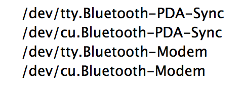
If this is your first time you’ve ever compiled code to your Arduino before plugging it in to the computer go to the Tools menu, then Serial Port and take note of what appears there.
Here’s what mine looks like before plugging in the Arduino UNO:
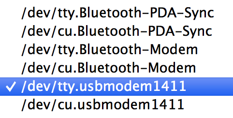
Plug your Arduino UNO board in to the USB cable and into your computer. Now go back to the Tools > Serial Port menu and you should see at least 1 new option. On my Mac 2 new serial ports appear.
They tty and cu are two ways that computers can talk over a serial port. Both seem to work with the Arduino software so I selected the tty.* one. On Windows you should see COM followed by a number. Select the new one that appears.
Once you have selected your serial or COM port you can then press the button with the arrow pointing to the right.
Once that happens you should see the TX and RX LEDs below the L LED flash. This is the communication going on between the computer and the Arduino. The L may flicker too. Once this dance is complete your program should be running. And your LED should be off.
Now let’s try and switch it on using the HIGH constant.
1
2
3
4
5
6
7
8
9
10
11
int ledPin = 13;
voidsetup()
{
pinMode(ledPin, OUTPUT);
}
voidloop()
{
digitalWrite(ledPin, HIGH);
}
Press Upload again and you should see your LED is now on!
Let’s make this a little more interesting now. We’re going to use another method called delay() which takes an integer of a time interval in milliseconds, meaning the integer of 1000 is 1 second.
So after where we switch the LED on let’s add delay(2000) which is two seconds, then digitalWrite(ledPin, LOW) to switch it off and delay(2000) again.
1
2
3
4
5
6
7
8
9
10
11
12
13
14
int ledPin = 13;
voidsetup()
{
pinMode(ledPin, OUTPUT);
}
voidloop()
{
digitalWrite(ledPin, HIGH);
delay(2000);
digitalWrite(ledPin, LOW);
delay(2000);
}
Press Upload and you should see something like this:
What next?
The Arduino platform is an incredibly easy and versatile platform to get started with. It’s open-source hardware, meaning that people can collaborate to improve, remix and build on.
It’s the brains to some of the most popular devices that are driving the next Industrial Revolution, the 3D printer.
Watch Massimo Banzi, co-founder of the Arduino project, talk about How Arduino is Open-Sourcing Imagination below:
For some more inspiration check out Adafruit’s YouTube channel. Here’s an example of what to expect, in this video, Becky Stern builds an Electronic Piggy Bank.
And as Massimo Banzi says “You don’t need anybody’s permission to create something great.” So what you waiting for?