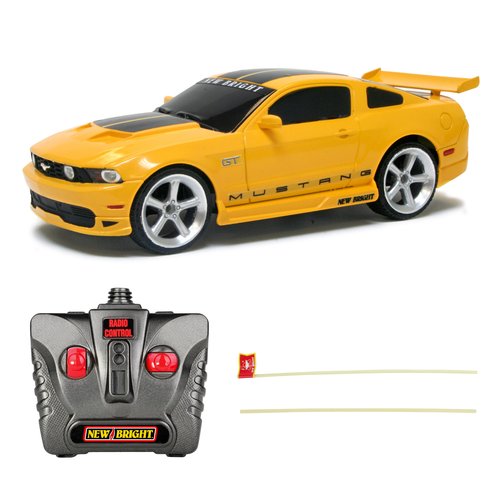
Last night I picked up a Ford Mustang 1:24 Scale Radio Control Sports Car from Walmart for under 9 bucks.
I’ve seen electronics enthusiasts and makers buy cheap RF cars and use parts for their projects. For example this cute Wall-E robot.
I wanted to see if I could use an Arduino to control the RC car.
Test Everything, All the Time
So before I did anything, I tested that the car actually worked. This is to determine if what I was going to do next didn’t break the thing.
I noticed when pressing forward/backward and left/right there was no granularity to the speed or turning. I heard clicking. It seemed there were just buttons controlling it. This means it should be fairly simple to hack and send signals from the Arduino.
Breaking In
So the first thing I did was remove the screw from the back (and a sticker) that would prevent me from opening up the remote.
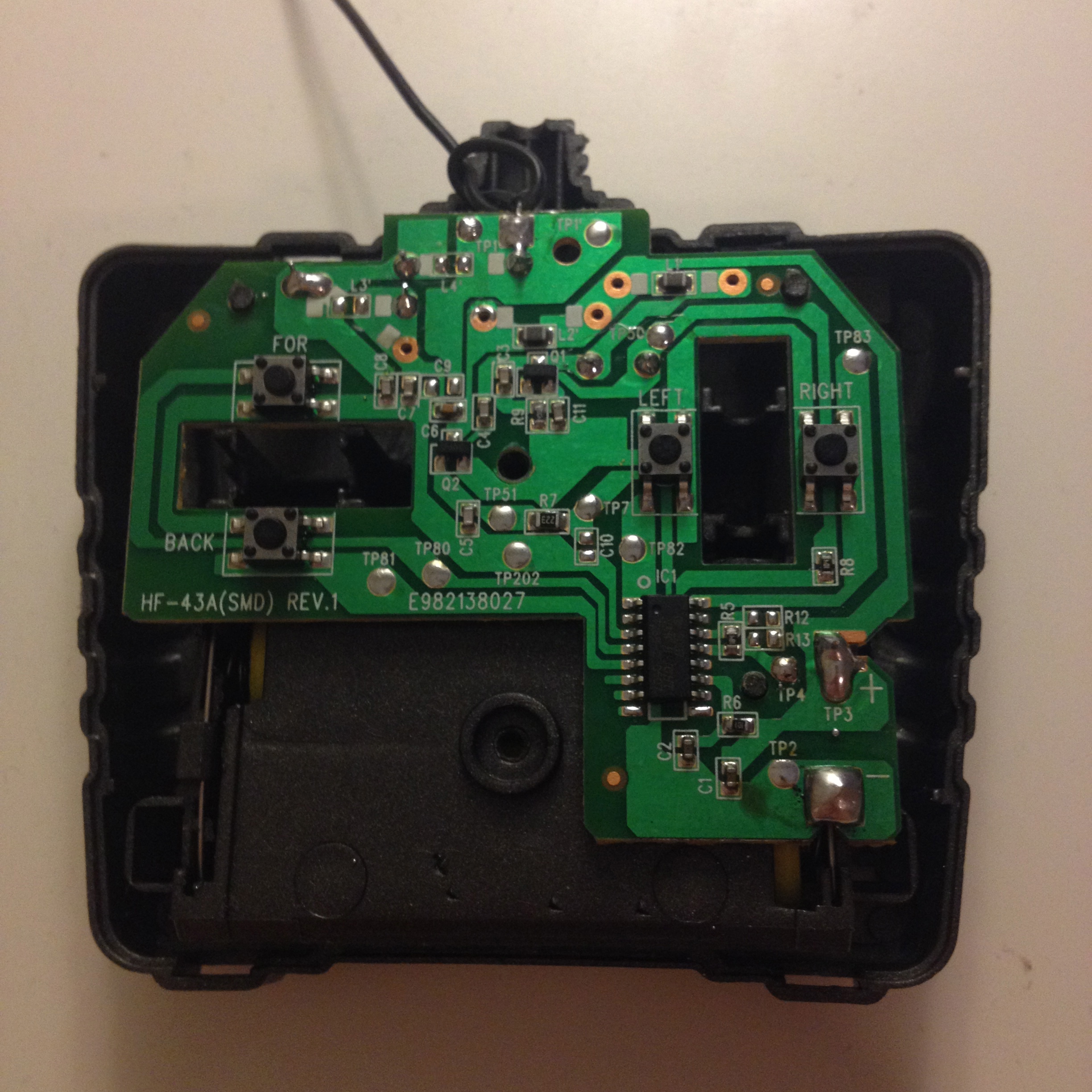
As you can see, as suspected, there are buttons for going forward (FOR), backward (BACK), left (LEFT) and right (RIGHT). I’ll use these later on. Whilst still attached to the back of the case I tested to see if pressing the buttons directly moved the car. It still worked.
Next, getting the remote off the dependancy of the two AA batteries so that the remote could be powered by the same source as the Arduino. Since each AA battery is 1.5V, the two will create a voltage of 3 volts. The Arduino has a 3.3V header, so I thought I could power the controller it with that.
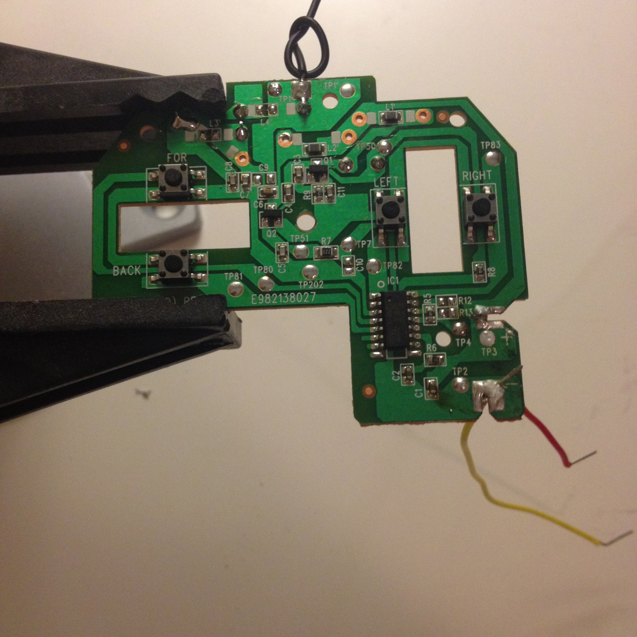
I desoldered the original connections to the battery compartment and soldered two wires, red to the positive and yellow to the negative (don’t have any black wire ;)).
I wired it up and pressed the buttons on the remote and the RC car still worked. At this point a second car that I got for my daughter to play with started moving slightly in response to the button presses. My car is at 27 MHz and my daughter’s is at 49 MHz. So I don’t know if exposing the circuit is causing interference with the other car or if I damaged it in someway. However, the signals from her controller overrides my interference so there’s not a big issue here.
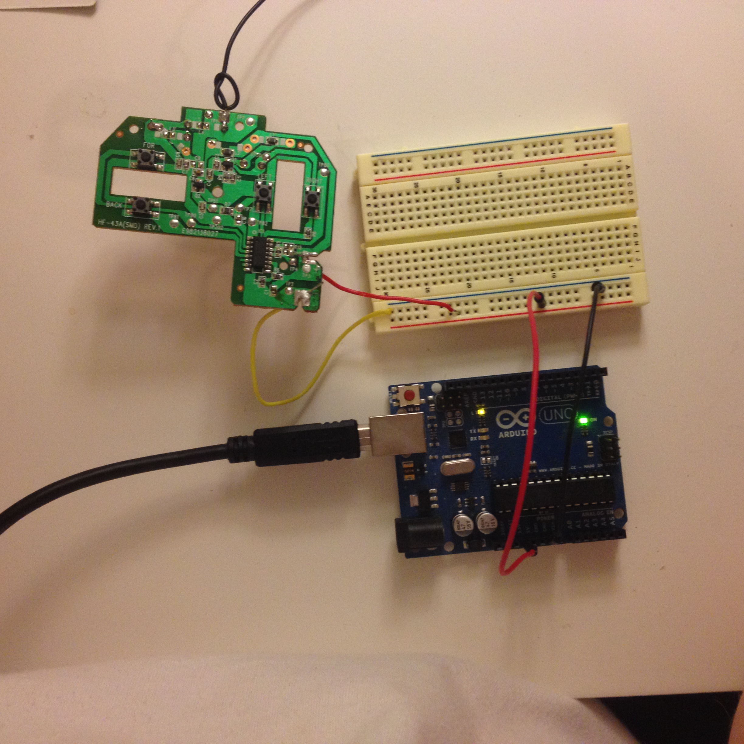
So now I had the power working, now on to programatically pressing the movement buttons. I could have desoldered the buttons and added another wire in it’s place but I followed the switch wire back around to a spot on the circuit board that said TP80. Now there’s several of theres TP points all over the circuit board. I thought that these could be places on the board that could be used for testing circuit boards during manufacture. Maybe some sort of test point? So I soldered a wire on to TP80 to see if I could programatically send a HIGH or LOW signal to pin 13, like the “blink” of controlling a RC car and I got the following result:
It went forward for a second stopped for a second and so on until it hit an object! Not bad! And the buttons are still in tact too!
So I wired up TP81 to pin 12 and made the car go backward and forward for one second. And yep it worked.
Conclusion
And that’s where I got up to last night. Being an absolute beginner to electronics and getting an off-the-shelf product like this to be programmable is pretty amazing and fulfilling.
The only thing that’s stopping anyone from doing anything like this, or anything for that matter, is themselves.
Getting a remote control car for under 9 bucks is way cheaper than building something like this from scratch.
Next Steps
I want to be able to programatically turn the car and who know’s what else? Maybe using computer vision libraries to process video from a webcam and talk down a serial connection to the Arduino to control the car automatically? Any ideas? Let me know.
Code
The code for this project and it’s dependancies can be found below:
- BasicLibrary - used for the object orientated interface with digital/analog pins
- RC_Back_Forward - code for making the car go forwards for a second then backwards for a second